Free loop budget tool
4–20 mA loop power calculator
A two-wire 4–20 mA loop works when the supply covers the transmitter’s minimum voltage plus every I × R drop at full current. Required supply = transmitter minimum + receiver drop + other drops + wire drop + margin; maximum loop resistance = (supply − transmitter minimum − fixed drops) ÷ current in amps.
4–20 mA loop power calculator
Enter the supply, the transmitter’s minimum terminal voltage from its manual, and what else sits in series. Design current is usually 20 mA; use 22 or 23 mA if alarm or saturation currents must also be powered.
- Shunt voltage at design current
- 5 V
- Shunt voltage at 4 mA
- 1 V
- Wire drop
- 0.8 V
- Required supply
- 18.3 V
- Remaining compliance
- 6.7 V
- Max total loop resistance
- 625 Ω
- Max wire resistance
- 375 Ω
Required = 10.5 + 5 + 1 + 0.8 + 1 = 18.3 V · Max R = (24 − 10.5 − 1) ÷ 0.02 A = 625 Ω. The supply covers the loop with your margin.
Nothing you enter leaves your browser.
How does a 4–20 mA loop use its supply voltage?
In a two-wire loop the same current flows through everything in series: the power supply, the transmitter, the receiver’s input resistor, any loop-powered indicator or barrier, and the cable. Ohm’s law gives each resistor’s drop, V = I × R with I in amps. Whatever voltage is left after those drops is what the transmitter has to work with. Its data sheet states the minimum terminal voltage it needs (often called lift-off voltage); below that it cannot regulate the current, and readings flatten out near the top of the range.
The calculator applies the same four relations as the My LoopCal app’s loop utilities:
- Shunt drop = mA ÷ 1000 × Ω.
- Required supply = transmitter minimum + device drops + wire drop + margin.
- Remaining compliance = supply − transmitter minimum − device drops − wire drop.
- Maximum total resistance = (supply − transmitter minimum − fixed drops) ÷ (mA ÷ 1000); subtract the receiver to get the wire budget.
Worked example: a 24 V loop with a 250 Ω input
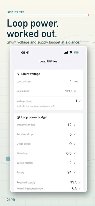
A pressure transmitter needs 12 V at its terminals. The PLC input card reads the loop across 250 Ω. The cable pair measures 25 Ω and you want 2 V of margin.
Receiver drop at 20 mA: 0.020 × 250 = 5 V
Wire drop: 0.020 × 25 = 0.5 V
Required supply: 12 + 5 + 0 + 0.5 + 2 = 19.5 V
Remaining compliance on 24 V: 24 − 12 − 5 − 0.5 = 6.5 V
Maximum total resistance: (24 − 12) ÷ 0.020 = 600 Ω, wire budget 350 Ω
The loop has comfortable headroom: you could add a loop-powered indicator dropping a few volts or run hundreds of ohms of extra cable before the transmitter runs short.
Worked example: a long run with an indicator, checked at 22 mA
A remote level transmitter needs 10.5 V, the loop passes through a field indicator that drops 3 V, the input resistor is 250 Ω, and the long cable run adds 260 Ω. The device sends 22 mA on a high alarm, so the budget is checked at 22 mA with a 1 V margin.
Receiver drop: 0.022 × 250 = 5.5 V · wire drop 0.022 × 260 = 5.72 V
Required supply: 10.5 + 5.5 + 3 + 5.72 + 1 = 25.72 V
Remaining compliance: -0.72 V (the margin wanted was 1 V)
Maximum total resistance: (24 − 10.5 − 3) ÷ 0.022 = 477.3 Ω, wire budget 227.3 Ω
On 24 V this loop is short: the cable alone exceeds the wire budget, so the transmitter would run out of voltage before reaching the alarm current. Options are a higher supply voltage where the devices allow it, a lower-resistance input, removing the indicator, or a heavier cable. The calculator highlights the result and says so whenever the supply does not cover the requirement.
What else belongs in a loop budget?
- Intrinsic-safety barriers and isolators add their own drop or resistance; take the figure from their data sheet.
- HART communication needs a minimum loop resistance for the signal to be read — at least 250 Ω for the Rosemount 3051, for example; check the device manual.
- Supply tolerance: a nominal 24 V supply may sag under load or temperature; your margin should cover it.
- Temperature: copper resistance rises with temperature, so long outdoor runs need extra headroom.
My LoopCal: 4-20mA Calibration includes these loop utilities free and without limit, alongside the signal converter. Its paid features add guided as-found and as-left checks, saved instruments and PDF worksheets. It is a calculation aid, not a calibrator, and it never connects to field equipment.
Sources
Questions people ask
What voltage does a 250 Ω resistor give in a 4–20 mA loop?
V = I × R: 1 V at 4 mA and 5 V at 20 mA, which is why a 250 Ω resistor turns a 4–20 mA loop into a 1–5 V input. A 500 Ω resistor gives 2–10 V.
How do I calculate the minimum loop supply voltage?
Add the transmitter’s minimum terminal voltage to every voltage drop in the loop at the design current — receiver or shunt, indicators, barriers, wire — plus any margin you want. With a 12 V transmitter, a 250 Ω receiver (5 V at 20 mA), 0.5 V of wire drop and 2 V of margin you need 19.5 V.
How do I calculate the maximum loop resistance?
R max = (supply − transmitter minimum voltage − fixed drops) ÷ loop current in amps. A 24 V supply and a 12 V transmitter at 20 mA allow (24 − 12) ÷ 0.020 = 600 Ω in total; with a 250 Ω receiver, 350 Ω is left for the wiring.
Which current should I design for: 20 mA or more?
Design for the highest current the transmitter can drive, not just 20 mA. Transmitters go above 20 mA for saturation and high alarm: the Rosemount 3051 guide lists 20.8 mA saturation and 21.75 mA alarm in Rosemount mode, 20.5 and 22.5 mA in NAMUR mode. Its maximum-load chart, 43.5 × (supply − 10.5 V), works out to about 23 mA. If the loop cannot carry the alarm current, the alarm is clipped.
What is compliance voltage?
It is the voltage left for the transmitter after all the other drops are taken from the supply. If remaining compliance falls below the transmitter’s minimum terminal voltage, the loop cannot reach full scale.
Does the calculator account for wire length?
Enter the total resistance of both conductors. Get it from the cable data sheet (ohms per 1000 ft or per km, multiplied by the loop length out and back) or measure it with the loop de-energized.