Free signal converter for instrument techs
4–20 mA scaling calculator
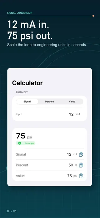
Engineering value = LRV + (signal − low) ÷ (high − low) × (URV − LRV). For 4–20 mA that is LRV + (mA − 4) ÷ 16 × span, so 12 mA is 50%. The calculator converts mA, volts or percent to engineering units and back, for direct or reverse action and linear or square-root ranges.
4–20 mA scaling calculator
Pick the signal type, enter the engineering range, then type a signal, a percent or an engineering value. All three update together, with the substituted formula.
- Signal
- 12.8 mA
- Percent of span
- 55%
- Engineering value
- 82.5 psi
- Status
- in range
signalFraction = (12.8 − 4) / (20 − 4) = 0.55engFraction = 0.55value = 0 + 0.55 · (150 − 0) = 82.5 psi
Nothing you enter leaves your browser.
How do you scale a 4–20 mA signal?
Any linear analog signal maps a signal span onto an engineering span. Work out how far the signal sits through its span (the signal fraction), then move the same fraction through the engineering range. The calculator above, and the My LoopCal app it mirrors, does it in this order:
- Signal fraction = (signal − signal low) ÷ (signal high − signal low).
- Direction: for reverse acting, acting fraction = 1 − signal fraction; otherwise it is unchanged.
- Transfer: linear keeps the fraction; square root takes √fraction.
- Engineering value = LRV + fraction × (URV − LRV).
The inverse — the signal a transmitter should send for a given process value — runs the same steps backward: engineering fraction, squared for a square-root range, inverted for reverse action, then mapped onto the signal span. Percent always means percent of the signal span, so 12 mA reads 50% whether the range is linear or square root.
The same formula covers 0–20 mA, 0–10 V and 1–5 V: only the endpoints change. A 1–5 V input is what you get when a 4–20 mA loop drives a 250 Ω resistor, so the percentages line up: 3.75 V on a 1–5 V input scaled 0–10 bar is 68.75% and 6.875 bar.
4–20 mA conversion table: linear and square root
Quick reference for a 0–100 range. The square-root column is flow as a percentage of full scale for a differential-pressure transmitter whose signal is linear in DP.
| Signal (mA) | Percent of signal span | Linear value (0–100) | Square-root value (0–100) |
|---|---|---|---|
| 4 | 0% | 0 | 0 |
| 8 | 25% | 25 | 50 |
| 12 | 50% | 50 | 70.711 |
| 16 | 75% | 75 | 86.603 |
| 20 | 100% | 100 | 100 |
Worked examples with real ranges
Temperature transmitter, −50 to 150 °C, reading 12 mA
(12 − 4) ÷ 16 = 0.5 → −50 + 0.5 × 200 = 50 °C
An offset range does not change the method; 0 °C sits at 8 mA here, not at 4 mA.
Pressure transmitter 0–100 psi: what current at 75 psi?
(75 − 0) ÷ 100 = 0.75 → 4 + 0.75 × 16 = 16 mA
DP flow transmitter with square-root extraction
12 mA: √0.5 = 0.7071 → 70.711% flow
50% flow: 0.5² = 0.25 → 4 + 0.25 × 16 = 8 mA
Because flow varies with the square root of differential pressure, small DP signals mean large flow changes near zero. Near zero flow a tiny DP error becomes a large flow error, so check how the transmitter and the control system treat the bottom of the range (many offer a low-flow cutoff setting) before you trust readings there.
Reverse-acting valve position, 0–100 %, signal 6 mA
(6 − 4) ÷ 16 = 0.125 → 1 − 0.125 = 0.875 → 87.5%
Where do scaling mistakes usually come from?
- Using 20 instead of 16 as the span. 4–20 mA has a 16 mA span; dividing by 20 makes every reading low.
- Mixing up the configured range. The transmitter, the DCS or PLC input and the indicator must share the same LRV and URV. Read them from the device, not from a drawing.
- Extracting the square root twice. If the transmitter already outputs flow, the control system must scale it linearly. Set square root in one place only.
- Clamping out-of-range signals. 3.6 mA or 21 mA may be a fault or alarm signal defined by the device; seeing the raw extrapolated value helps diagnosis.
From the conversion to a calibration record
My LoopCal: 4-20mA Calibration has this converter on its first tab, free and without limits, with the substituted formula under every result. “Verify this loop” carries the range straight into a guided check: expected output at each point, observed value, error, percent-of-span error and pass/fail against your tolerance, as found and, after adjustment, as left. The result is a PDF worksheet with your company name and logo. A new install includes one three-point as-found check; more checks, five-point and custom procedures, as-left runs, saved instruments and exports need an in-app purchase. The app is a calculation aid and field worksheet, not a calibrator: follow lockout/tagout, operations authorization and the manufacturer’s procedure.
Sources
Questions people ask
What is the 4–20 mA scaling formula?
Engineering value = LRV + (mA − 4) ÷ 16 × (URV − LRV). For a 0–100 psi transmitter, 12 mA gives 0 + 8 ÷ 16 × 100 = 50 psi. For other signals replace 4 and 16 with the signal’s low end and span.
What percentage is 12 mA in a 4–20 mA loop?
50%. Percent of span = (mA − 4) ÷ 16 × 100, so 8 mA is 25%, 12 mA is 50% and 16 mA is 75%.
How do I convert an engineering value back to milliamps?
mA = 4 + (value − LRV) ÷ (URV − LRV) × 16. On a 0–100 psi range, 75 psi needs 4 + 0.75 × 16 = 16 mA. Choose “Engineering value” in the calculator to do this for any range.
How does square-root extraction change the result?
For differential-pressure flow, differential pressure rises with the square of flow (ΔP ∝ Q²), so flow % = √(signal fraction) × 100. At 12 mA (50% of the DP signal) the flow is about 70.7% of full scale; 25% flow needs only 6.25% DP, or 5 mA.
What does reverse acting mean?
Rising signal means falling engineering value: 4 mA is the top of the range and 20 mA the bottom. The calculator applies 1 − fraction before scaling, the same order the LoopCal app uses.
What happens below 4 mA or above 20 mA?
The result is extrapolated and flagged as under or over range rather than clamped, so you can see how far out the loop is. A square-root range has no real result below live zero and shows an explanation instead.